Identify your ECU with dreamKIT
In this section, we will help you to identify the requirements to successfully connect an ECU to dreamKIT. The necessary information will consists of the dreamKIT hardware specifications and the communication identifiers on your ECU.
What you will achieve
By following this guide, you can register any ECU to the dreamKIT. You will be confident to connect any ECU for your own development purpose.
1. dreamKIT hardware specifications
Currently, our dreamKIT supports Controller Area Network (CAN) bus, both Standard CAN and CAN-FD. Please ensure your ECU has CAN protocol.
1.1. Explore the CAN communication ports
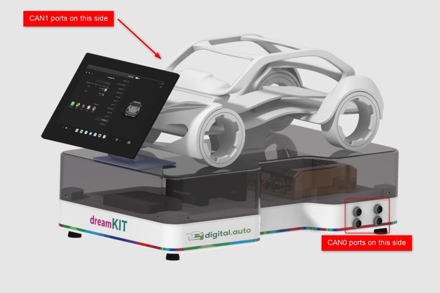
The CAN communication on your dreamKIT is divided into two groups of ports: CAN0 group and CAN1 group. Below, you will find an illustration showing the exact location of these ports:
1.2. Default CAN configurations
Below are the default settings of the CAN buses on dreamKIT. This defines how the CAN ports operate out of the box. Starting a project with the default configurations will minimize the setup process:
| CAN0 | CAN1 | |
|---|---|---|
| Type | CAN FD | Standard CAN |
| Data rate | 500/2000 kbps | 500 kbps |
| Data length | up to 64 bytes | up to 8 bytes |
1.3. Anatomy of a CAN port
Each CAN port consists of 6 pins:

| Pin | Function |
|---|---|
| 1 | CAN LOW (CANL) |
| 2 | CAN HIGH (CANH) |
| 3 | VCC |
| 6 | GND |
Each connector is created not only to provide a stable 12V power supply but also to support CAN communication between the dreamKIT and connected ECUs. This dual functionality simplifies the connections between the hardware during our development process.
2. Configure the CAN settings
While the default configuration of the dreamKIT’s CAN ports is designed to meet a wide range of needs, specific projects may require custom settings. If the default settings do not align perfectly with ECU’s requirements, you have the flexibility to modify these settings to better suit your project’s demands.
The configuration options for the CAN settings are accessible through the S32G Gateway. To customize these settings, you’ll need to establish a secure remote connection. Here’s how you can get started:
- Establish an SSH Connection:
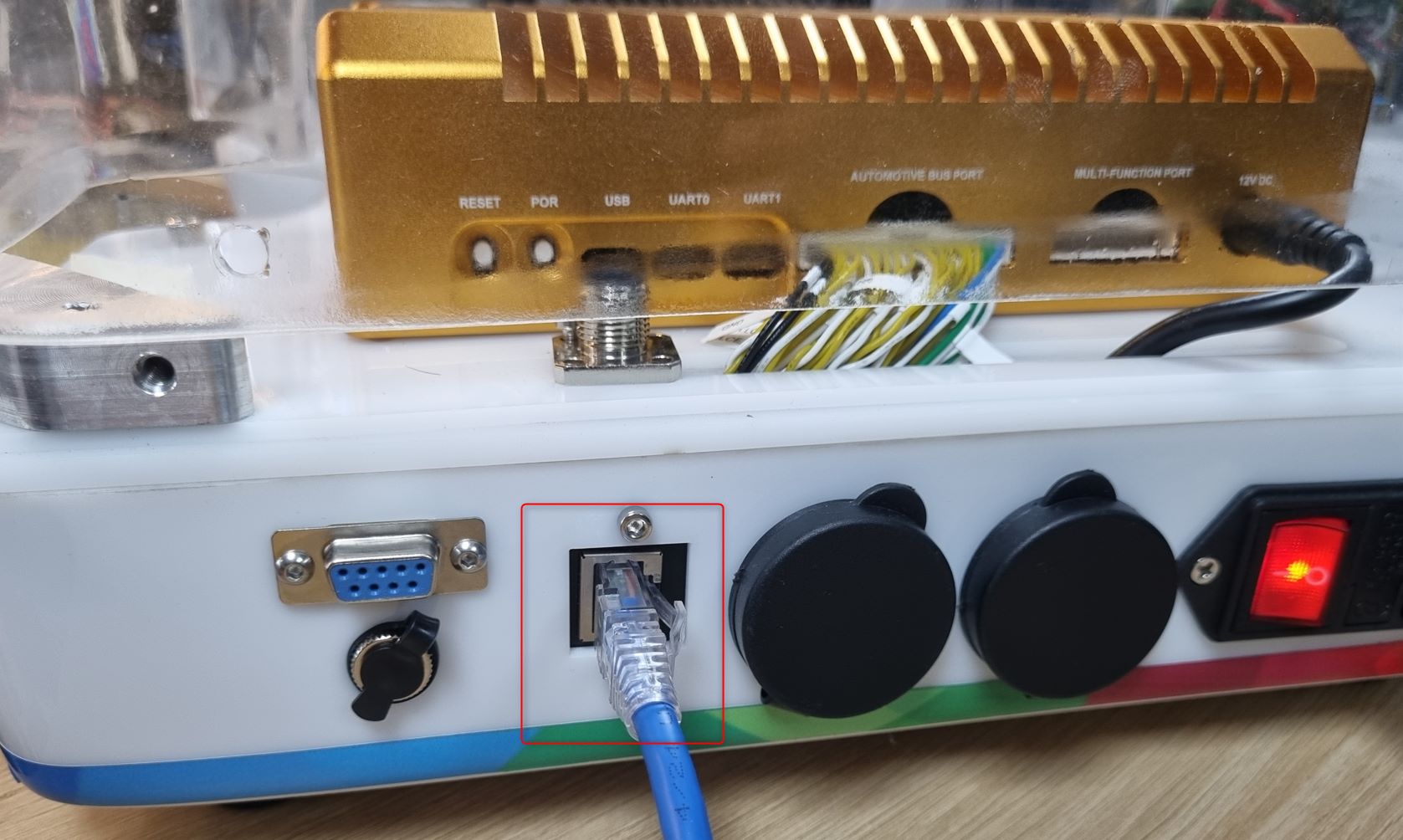
First, an RJ45 Ethernet cable is used to link the dreamKIT to our PC:
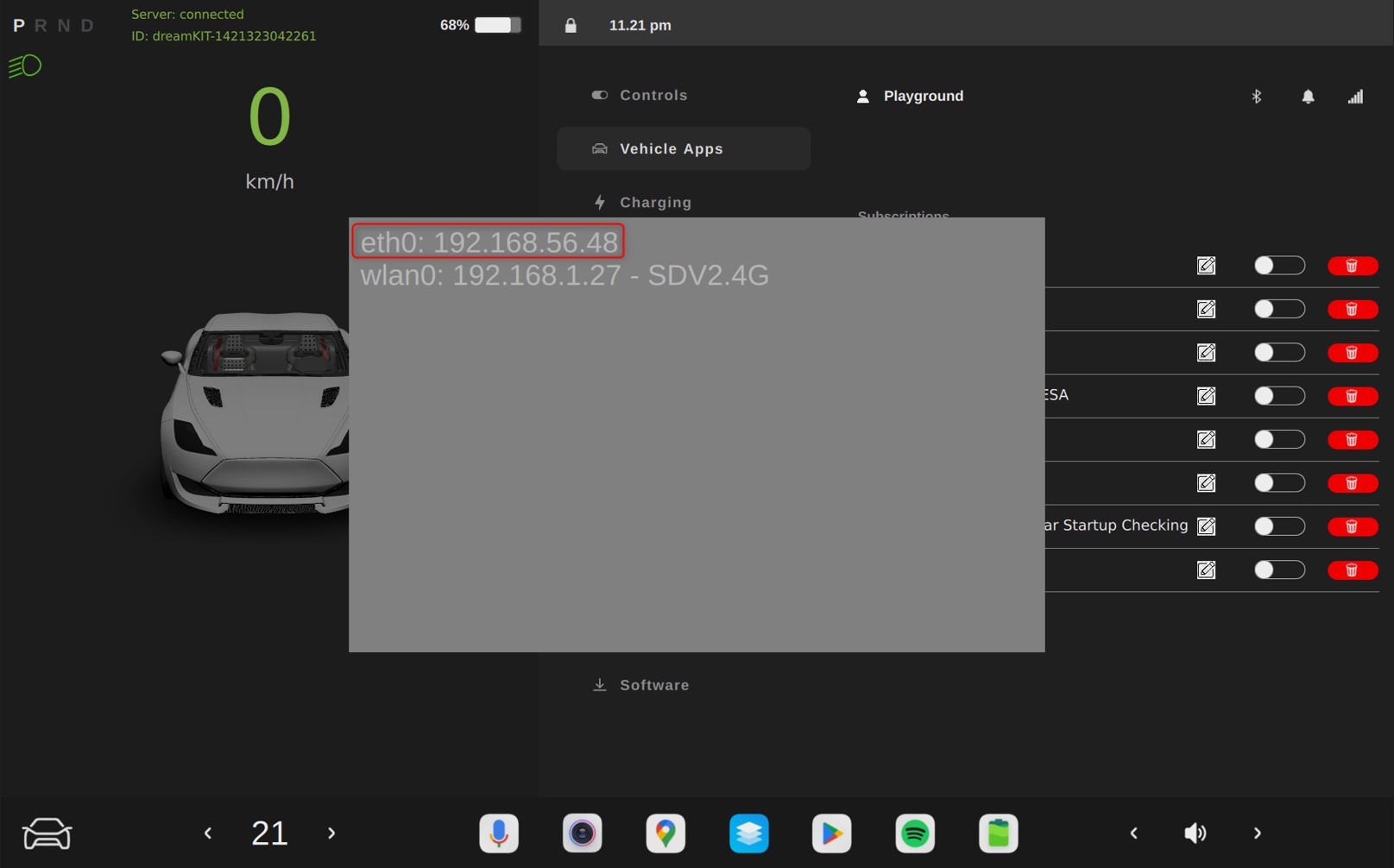
Have a look on the dreamKIT’s IVI, we can observe the pre-defined Ethernet IP provided by our dreamKIT:
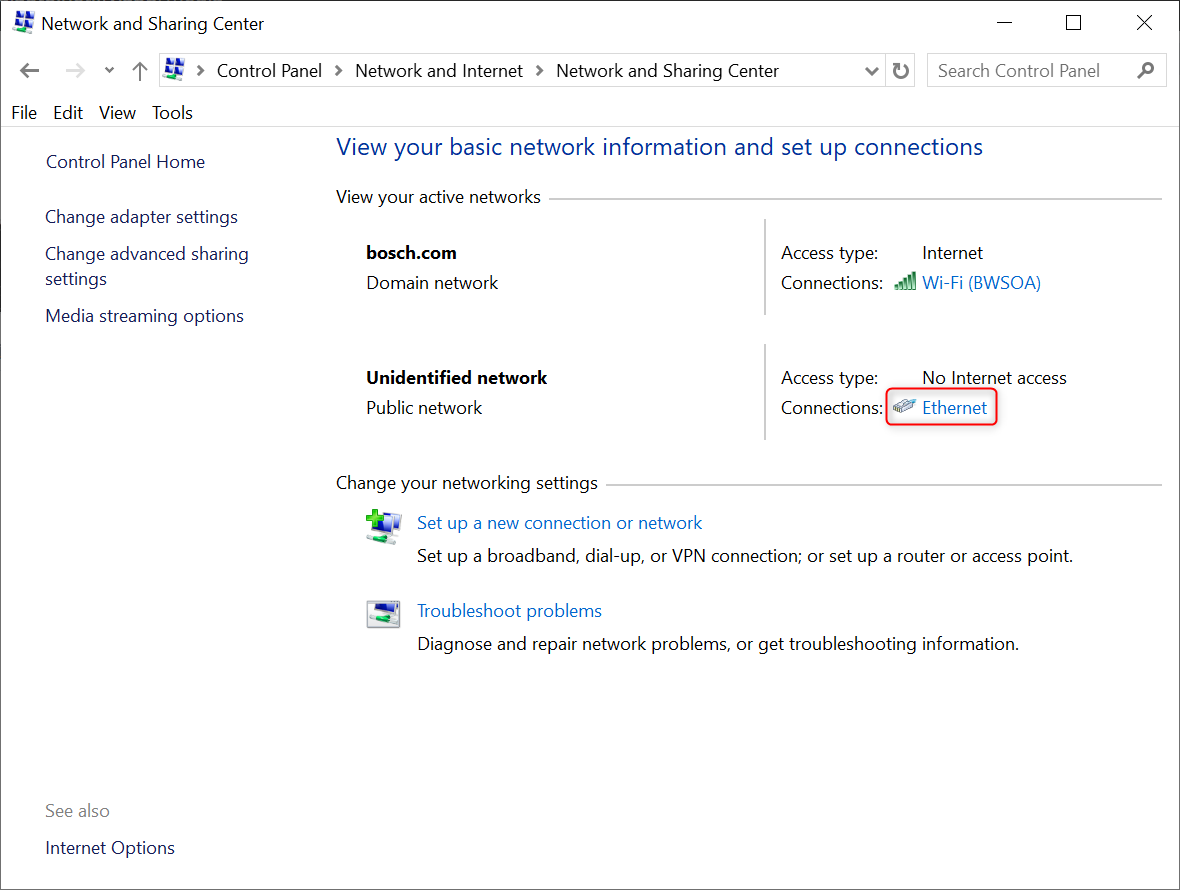
For our PC to recognize this Ethernet connection, we need to reconfigure the IP address on the Ethernet port of our PC to have the same network 192.168.56.xx/24. We can do it by following the steps on our Windows PC: Control Panel -> Network and Internet -> Network and Sharing Center, then follow up with the steps below:
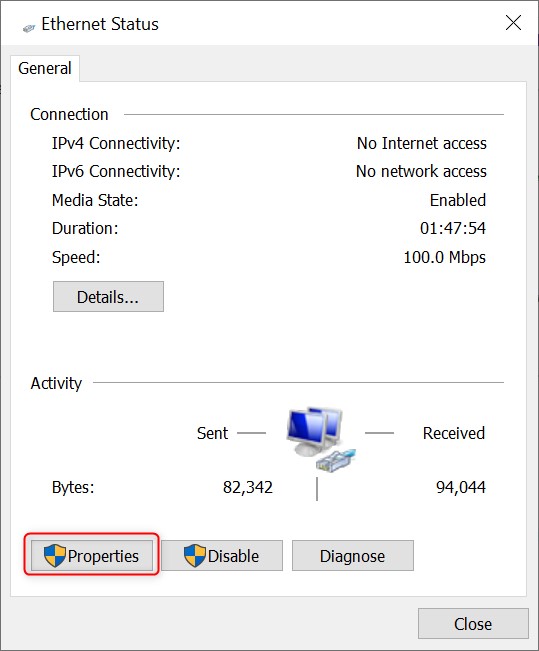
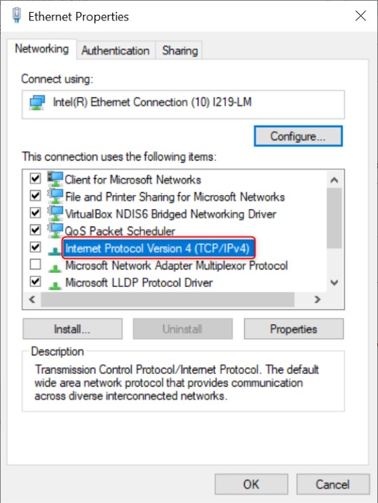
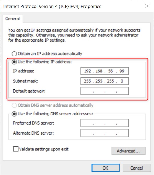
By ensuring both your PC and the dreamKIT are configured to the same subnet of 192.168.56.00/24, data exchange and connectivity is allowed across the network.
- Setting up an SSH connection to the Gateway:
This secure method ensures that your adjustments are safe and private. The command format is: $ ssh [username]@[host_ip_address].
- Access Credentials:
To obtain the necessary username and host_IP_address for the Gateway, please have a look at the table below. The information will be used again and again during your work with dreamKIT, so please note it somewhere easy to access.
| Jetson Orin VCU | S32G Gateway | |
|---|---|---|
| username | sdv-orin | bluebox |
| host_IP_address | 192.168.56.48 | 192.168.56.49 |
| password | 123456 | 123456 |
Note: If you lack any information while following this guide, please feel free to contact our support team. They are ready to assist you with the information you need to access your system.
To SSH to your Gateway:
$ ssh bluebox@192.168.56.49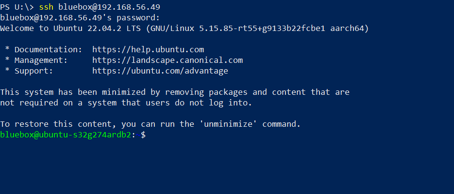
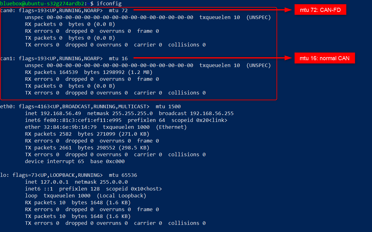
Our default CAN protocols will have the properties like this:
- Make some changes to the CAN settings:
- To apply changes to a CAN interface, first disable it with:
$ sudo ip link set [your_can_interface] down - Configure the CAN interface:
- For a standard CAN interface:
$ sudo ip link set [your_can_interface] type can bitrate [your_desire_bitrate]. - For a CAN-FD interface:
$ sudo ip link set [your_can_interface] type can bitrate [your_desire_bitrate] sample-point [sample_rate] dbitrate [CAN_bit_rate] fd on.
- For a standard CAN interface:
- Lastly, you will need to re-enable the CAN interface:
$ sudo ip link set [your_can_interface] up. Now your settings should be applied successfully.
Example configuration
Suppose you want to switch your CAN1 interface from standard CAN to CAN-FD with a bitrate of 100000. After disabling the CAN1 interface, you would use the command:
$ sudo ip link set can1 type can bitrate 100000 sample-point 0.75 dbitrate 2000000 fd onThen, reactivate it and check the modifications:
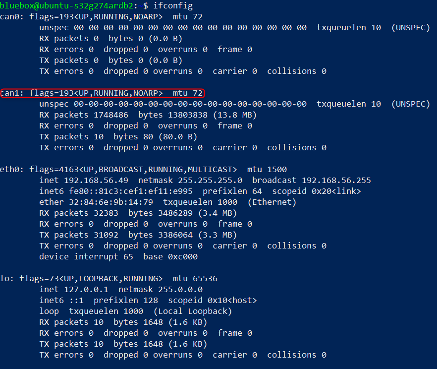
Now, your CAN1 interface should show the maximum transmission unit (MTU) of 72, confirming that it is operating under the CAN-FD protocol!
3. Register your ECU to dreamKIT
3.1. ECU information fields in EcuList.json
The detailed registration information for each ECU connected to the dreamKIT is meticulously stored in the EcuList.json file, which is located in /opt/data/ by default on both the VCU and the Gateway of your dreamKIT system.
This critical file contains all the registered ECU information, enabling the dreamKIT to accurately recognize and identify each connected ECU along with its specific properties. To effectively integrate an ECU with your system, you must provide the following key information fields in the EcuList.json:
| Field name | Description |
|---|---|
| “name” | This is the name of your ECU |
| “comType” | Type of communication |
| “channel” | Channel of the communication type |
| “reqToEcuID” | Request to ECU ID |
| “resFromEcuID” | Response from ECU ID |
| “triggerMsgID” | Trigger Message ID |
| “pathToSecCheck” | Path to the security file |
| “DID_Info” | Data Identifier (DID) of the UDS protocol on ECU |
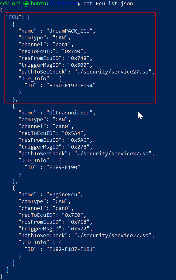
Your EcuList.json file should looks like this:
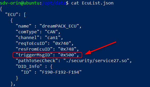
One essential parameter to focus on is the “triggerMsgID”. This ID is periodically sent by the ECU and serves as a unique identifier for the dreamKIT to acknowledge the presence and identity of the connected ECU.
In our specific scenario, when the dreamKIT receives a CAN message with the ID value of 0x500, it identifies the connected ECU as the dreamPACK_ECU. This ID acts as a signature, allowing the dreamKIT to distinguish the dreamPACK_ECU from other devices and ensuring that all interactions and communications are correctly attributed and processed.
By setting and monitoring the “triggerMsgID”, the dreamKIT can effectively manage multiple ECUs, each potentially with its unique identifier, thus enhancing the system’s ability to scale and accommodate diverse automotive applications.
3.2. Updating the EcuList.json file in dreamKIT
Once you have filled in all necessary details for your ECU in the EcuList.json, ensure that this file is updated on both the VCU and the Gateway to maintain system consistency.
To facilitate file transfers between the VCU and the Gateway, we use the scp command. This command allows for the secure copying of files across the network:
$ scp -r '/source_path/source_file_folder' '/destination_path/destination_file_folder'After filling your ECU information into the EcuList.json file, you need to synchronize and update the EcuList.json on both the VCU and the Gateway. Suppose that you are adding your ECU to the list in the Gateway, then you will need to copy that EcuList.json from the Gateway to the VCU by using this command line:
$ scp -r '/opt/data/EcuList.json' 'sdv-orin@192.168.56.48:/opt/data/'3.3. Restart dreamKIT to apply changes
After updating your ECU information and synchronizing the EcuList.json file between the Gateway and the VCU, you need to restart the dreamKIT so that changes can be applied to our system. You just need to toggle the physical power switch on the dreamKIT. The ECU that you have configured should then be recognized automatically.
4. Plug your ECU into the dreamKIT
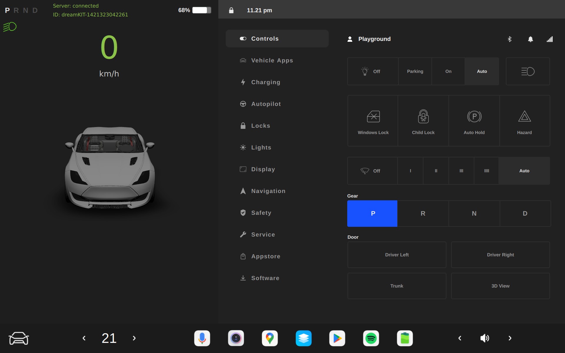
Upon successfully powering up your dreamKIT, the In-Vehicle Infotainment (IVI) will display as follows:
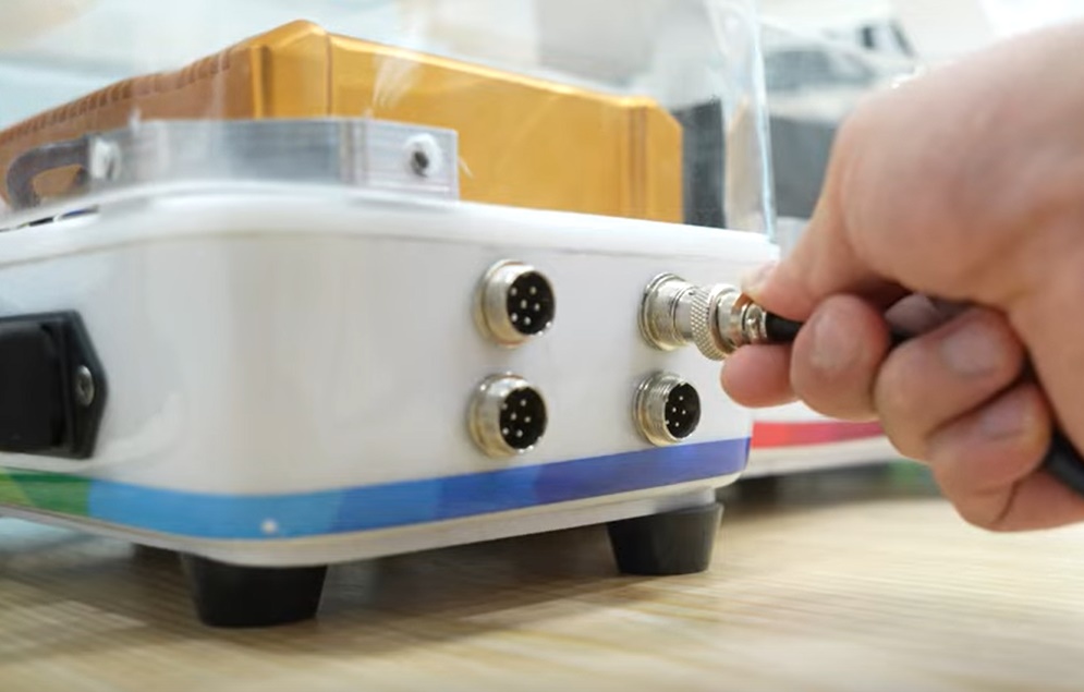
Each ECU connects to the dreamKIT using one of the combined power and CAN ports of your choice:
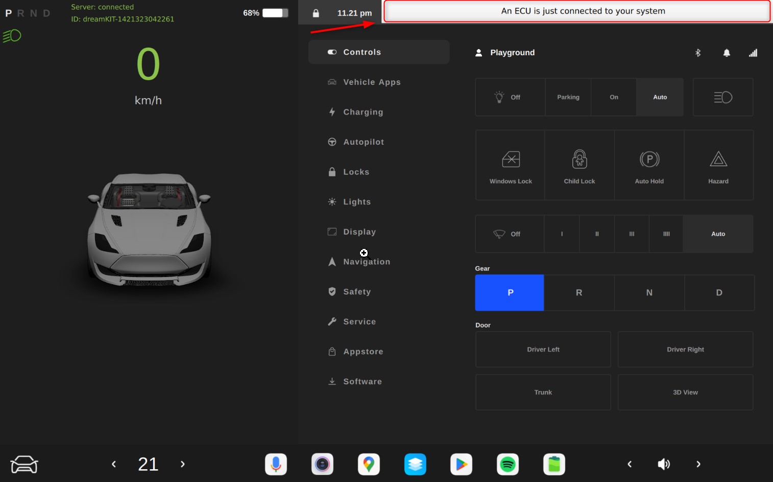
Internally, the dreamKIT’s software immediately begins checking for the periodically sent “triggerMsgID” sent from any connected ECUs. This ID helps the system recognize whether the connected ECU has been predefined in the system’s configuration.
If the ID matches a predefined one, the IVI will display a notification: “An ECU is just connected to your system”:
Under the “Service” tab on the IVI, you can view both registered and currently connected ECUs:
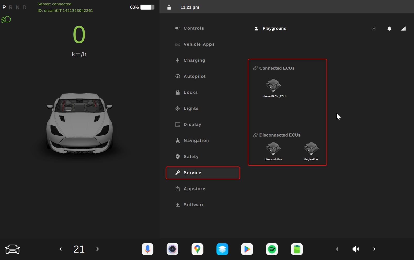
When a registered ECU, like the dreamPACK, connects and communicates using specific CAN messages (e.g., ID 0x500), the dreamKIT identifies and displays the ECU’s details on the IVI under the “Service” tab.
Need assistance? Contact our development team
Should you have further interest in dreamKIT, please send us query here https://forms.office.com/e/BiJcMEhbBy
Our team is committed to providing you with the necessary support to address your queries and challenges promptly.